
USB 3.0 camera modules are widely used in industrial inspection, machine vision, medical imaging, robotics, research, and high-quality consumer devices. Compared with USB 2.0, USB 3.0 provides much higher bandwidth (up to 5 Gbps), lower latency, and more reliable data transfer, enabling higher resolution, higher frame rates, or both. This article explains how to choose the right USB 3.0 camera module and describes common application scenarios.
Why Choose USB 3.0?
- Higher bandwidth: Up to 5 Gbps enables uncompressed transmission of high-resolution or high-frame-rate video.
- Lower latency: Faster transfer reduces end-to-end delay, important for real-time systems.
- Power delivery: USB can provide power to compact modules, simplifying system design.
- Ubiquity: USB connectors and drivers are widely supported on PCs, embedded systems (with USB 3 ports), and some single-board computers.
- Cost-effective: Compared with specialized interfaces (e.g., Camera Link, CoaXPress), USB 3.0 is often more affordable while offering sufficient performance for many applications.
Key Specifications to Consider
When selecting a USB 3.0 camera module, evaluate the following technical parameters to match your application needs.
- 1. Sensor Type and Size
- CMOS vs CCD: Most modern USB 3.0 modules use CMOS sensors (lower power, higher integration). CCDs may still be used in niche imaging requiring low noise.
- Sensor size: Larger sensors generally provide better low-light sensitivity and dynamic range. Common sizes: 1/3″, 1/2.8″, 2/3″, 1″, APS-C.
- Pixel size: Larger pixel area collects more light (better sensitivity, lower noise). Trade-off between resolution and per-pixel sensitivity.
- 2. Resolution and Frame Rate
- Resolution: From VGA and HD to multi-megapixel sensors (2MP, 5MP, 12MP, 20MP+). Choose based on detail required.
- Frame rate: High-speed vision may need 60, 120, 240+ fps at lower resolution. Consider sensor readout and USB 3.0 bandwidth limitations.
- Bandwidth planning: Calculate required bandwidth: Width × Height × Bits per pixel × Frame rate. Ensure combined streams fit under USB 3.0 throughput (practical ~3–4 Gbps after overhead).
- 3. Pixel Format and Bit Depth
- Mono vs Color (Bayer*: Monochrome for higher sensitivity and detail in many machine vision tasks; Bayer/color for natural scenes.
- Bit depth: 8-bit is common; 10/12/14-bit yields higher dynamic range and finer tonal steps, useful in scientific imaging.
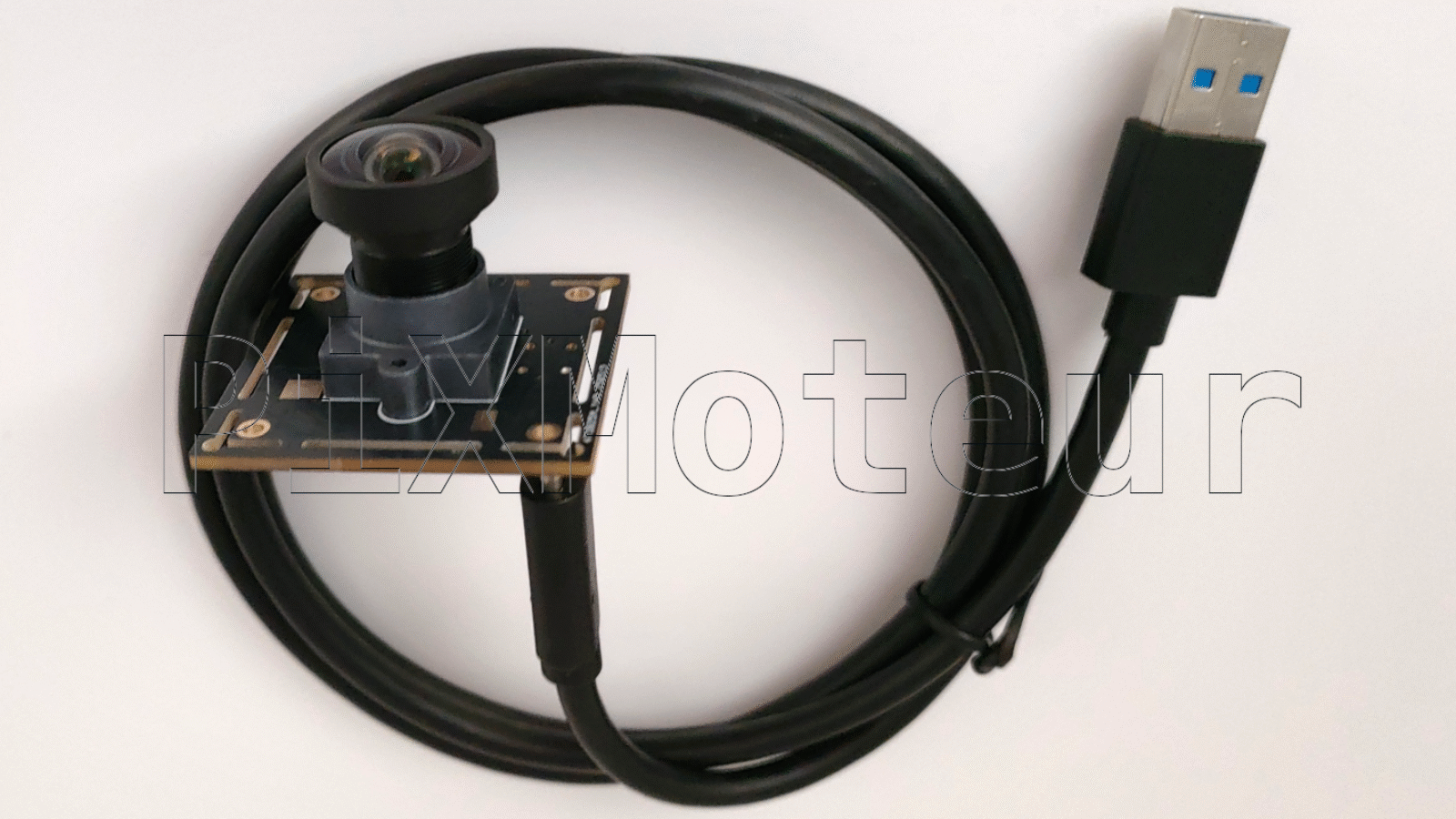
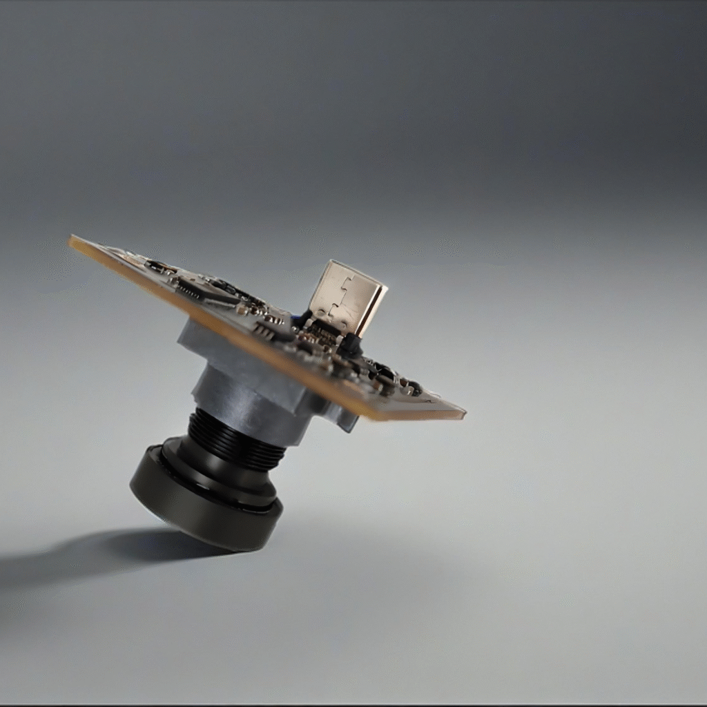
- 4. Interface and Protocol
- USB 3.0 physical: SuperSpeed USB Type-B or Micro-B connectors; ensure cable quality and shielding.
- Protocol: Many modules use USB3 Vision (GenICam) standard — simplifies driver and software support. If USB3 Vision compliance is required, confirm the module supports GenICam and has compatible drivers.
- Driver support: Check OS support (Windows, Linux, macOS) and SDK availability (C/C++, Python bindings, wrappers for OpenCV).
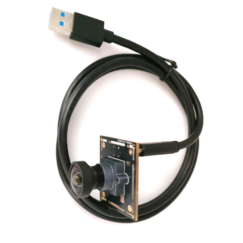
- 5. Lens Mount and Optics
- Mount type: C-mount, CS-mount, board-level lens, M12 (S-mount), or fixed optics. Choose based on lens selection and focus distance.
- Field of View (FOV): Determine lens focal length to achieve required FOV for sensor size and working distance.
- Global shutter vs rolling shutter:
- – Global shutter_: Captures whole frame at once — essential for high-speed moving objects to avoid motion artifacts.
- – Rolling shutter_: Cheaper and common in CMOS sensors, but can introduce distortion with fast motion or scanning illumination.
- 6. Exposure and Gain Control
- Manual and automatic exposure: For varying lighting environments, automatic exposure and gain help; manual control is required for consistent industrial setups.
- Triggering: Hardware trigger (TTL/trigger in) for precise capture timing, essential in synchronized multi-camera setups or strobe lighting.
- 7. Synchronization and Multi-Camera
- Trigger in/out, Genlock: For multi-camera systems, hardware sync (triggers, sync signals) keeps frames aligned.
- External I/O: Opto-isolated inputs/outputs or TTL signals for robust industrial interfacing
Leave A Comment